Simplified Hardware Arx
I’m taking an online workshop on building electronic musical instruments. So last week I put together a sketch, in blog post form, of what it might look like to make a hardware Arx — which is to say, a hardware version of my Ruby breakbeat improviser Archaeopteryx (renamed for simplicity).
Here’s the basic design I came up with.
These dimensions weren’t exact. This was just a way to flesh out the UI controls. But I wanted to get specific about the controls so I could figure out what parts to buy from SparkFun.
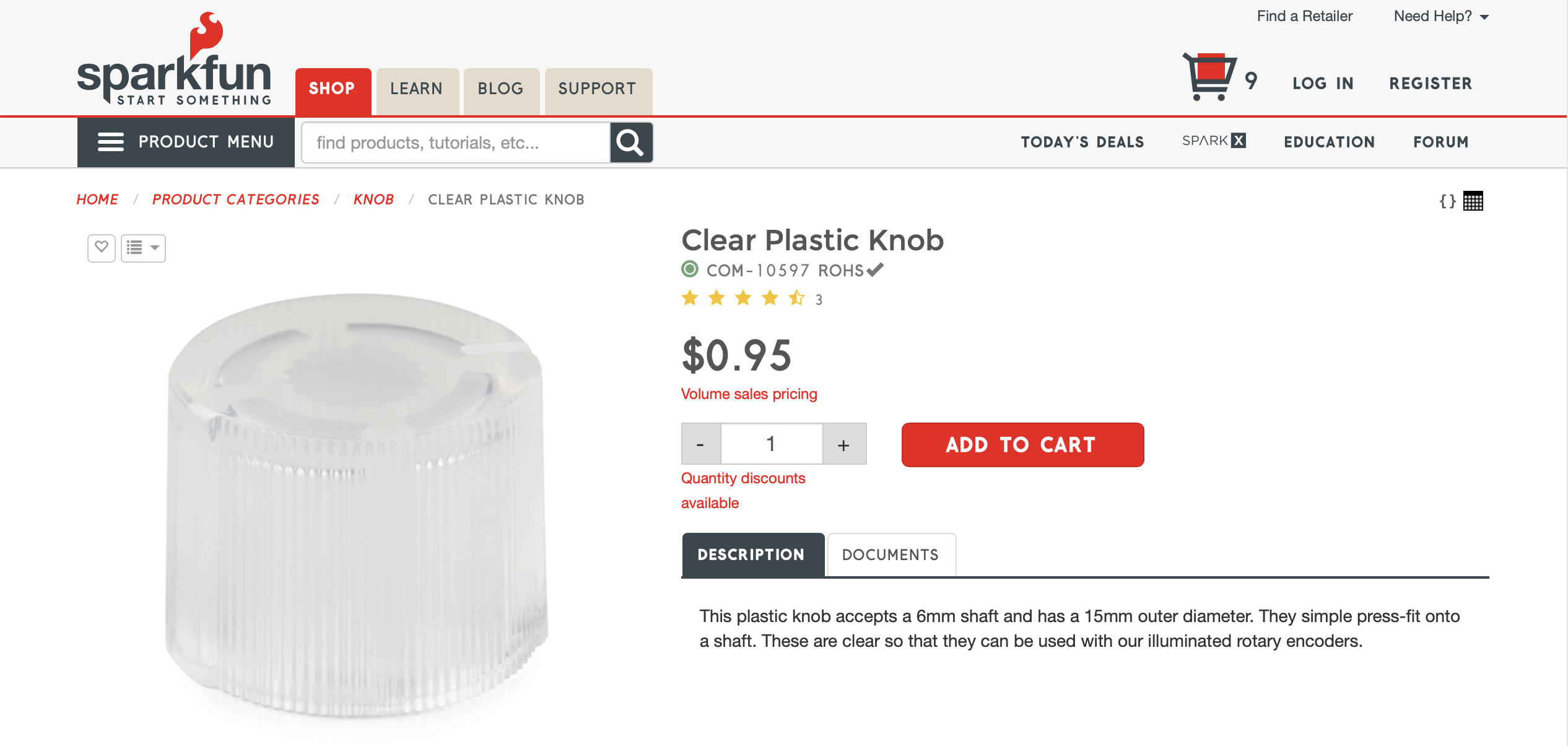
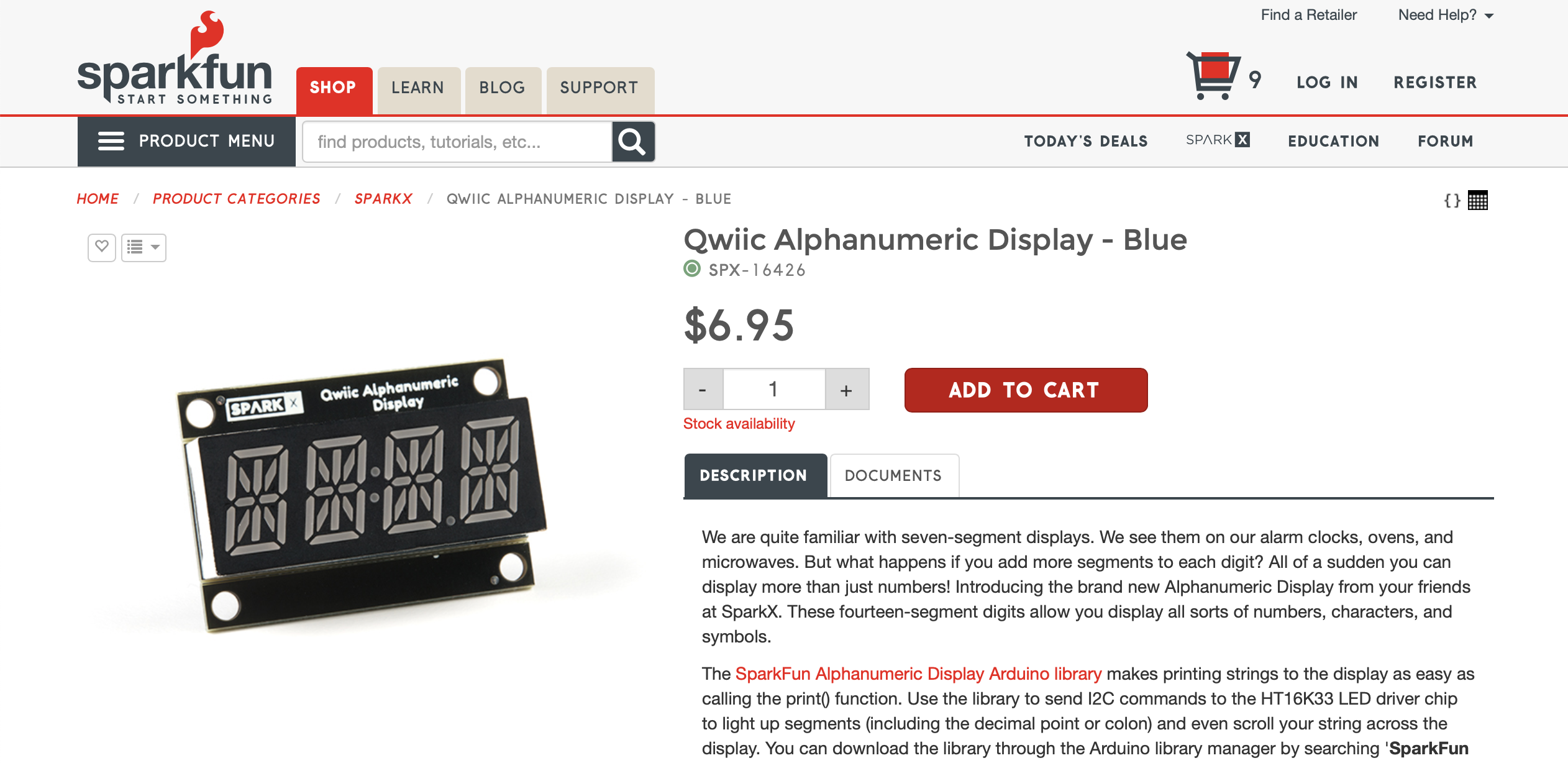
These are the parts I had in mind: a pushbutton rotary encoder with built-in RGB LEDs, a transparent plastic cap, a membrane potentiometer (a touch strip), and a 14-segment display.
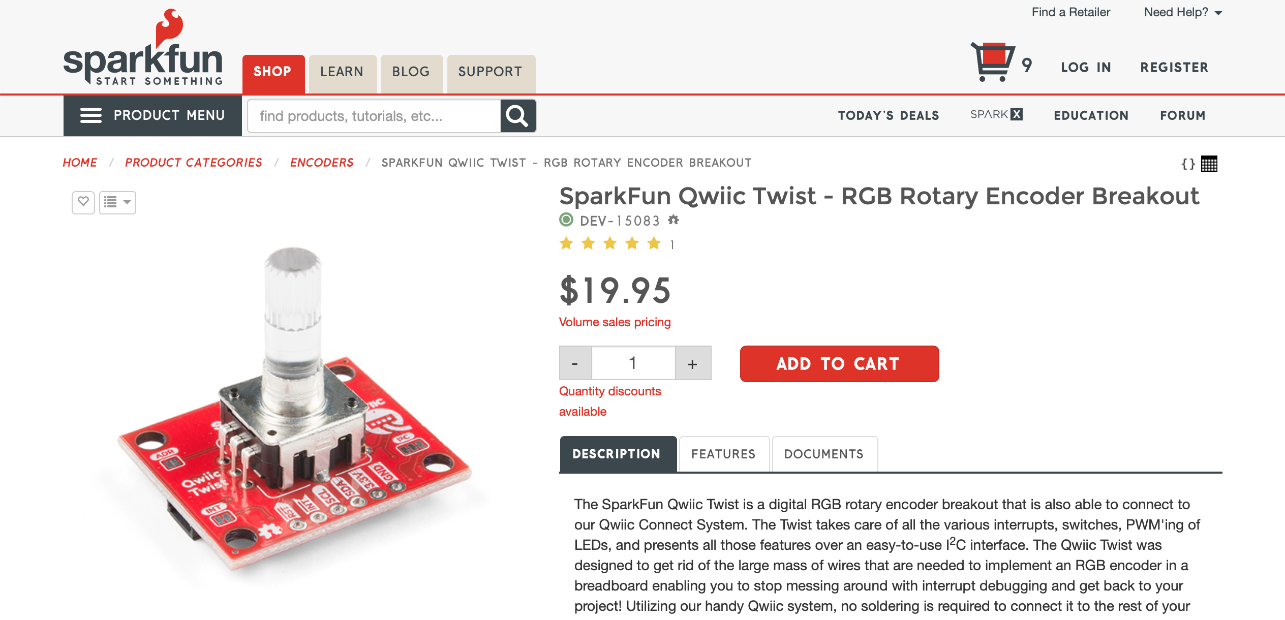
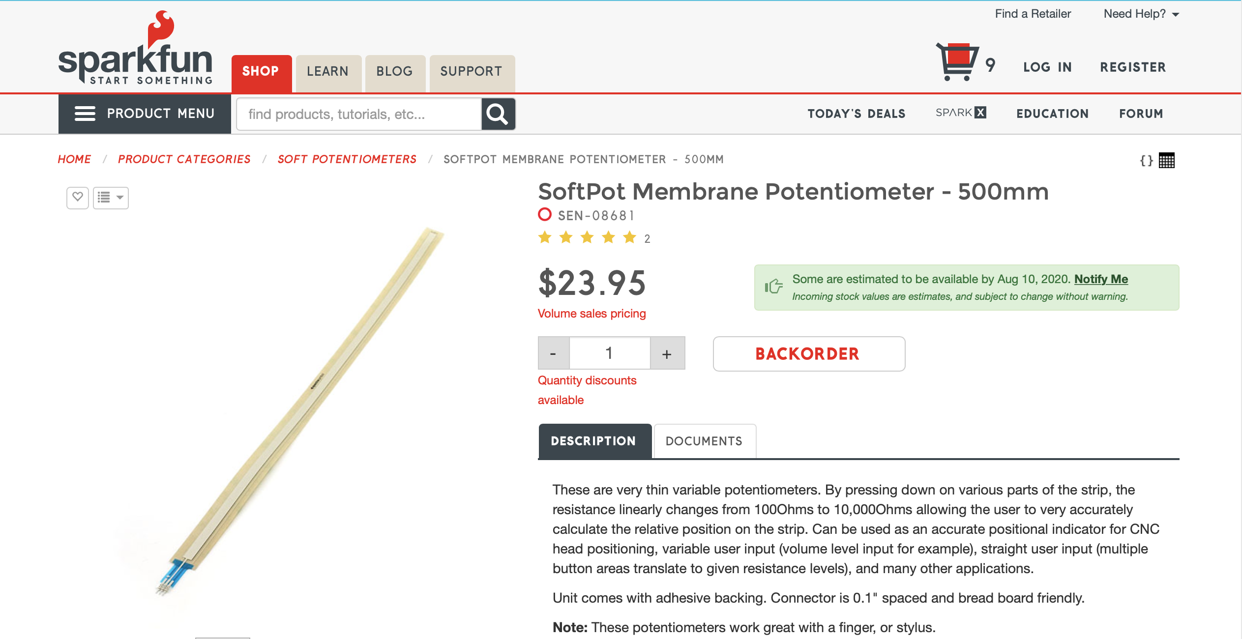
But my design has 17 encoders, and at over $20 apiece (if you count the caps), that’s well over $300, just for an experiment. Also, although I’ve built some stuff from kits — including a Moog Subharmonicon — I still don’t really know what I’m doing. Finally, SparkFun didn’t have the touch strip I wanted in stock, but they did have a shorter one. So I came up with a simpler design that will still allow me to build a 4-drum, 16-beat Arx, but which has fewer moving parts.
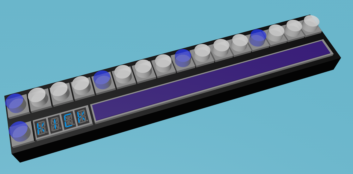
Here’s the new, simpler design:
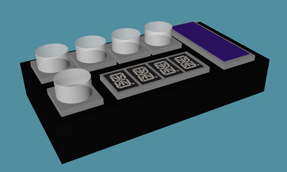
This design still uses the display, and the encoder beside it, for a menu-driven interface, and it still uses the touch strip to override the probability generation and provide values manually. This allows you to switch between a generative approach and a more hands-on, layer-oriented approach, as I explained in the previous post. Long story short, the display, its encoder, and the touch strip all still function as in the original design.
The main thing which changed is the purpose of the top row of knobs. In most drum machine designs, that usually represents the number of beats. For instance, consider this basic drum pattern:
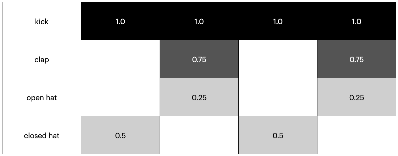
You might implement that by having each knob in the top row represent a beat:
Then you’d use the encoder next to the display to choose between the drums. In this type of UI, the row of buttons represents a row in the drum grid above. This is how most drum machines work. But if I did it that way, I’d only get a 4-step sequencer out of it. Each individual button would represent a column, which is to say a beat, and there’s only four of them. That’s pretty much only fit for polka, military marches, and extremely simplistic examples in blog posts. To make the kind of music I want to make, I want a 16-step sequencer at least. But if I’m starting with just 4 encoders (or really 5), then I can’t use a design which maps beats to encoders, one for one.
But you can also have each button represent an individual drum, and have the row of buttons map to a column in the drum grid. That’s what I plan to do. I’ll have each top row knob represent a drum, and let the user scroll through the beats using the display and its knob. So if your first beat has a kick drum (knob 1) and a closed hi-hat, per the grid diagram above, that first column in the grid might map to the row of encoders like this:
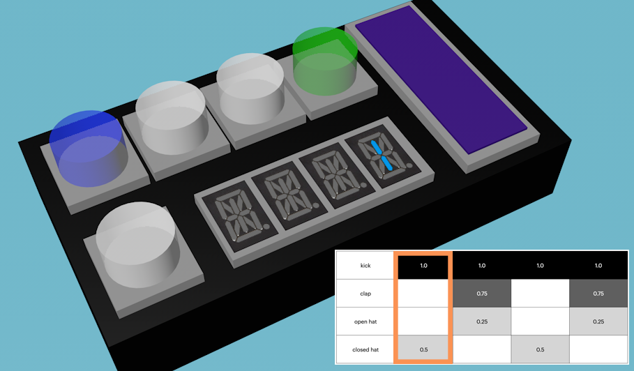
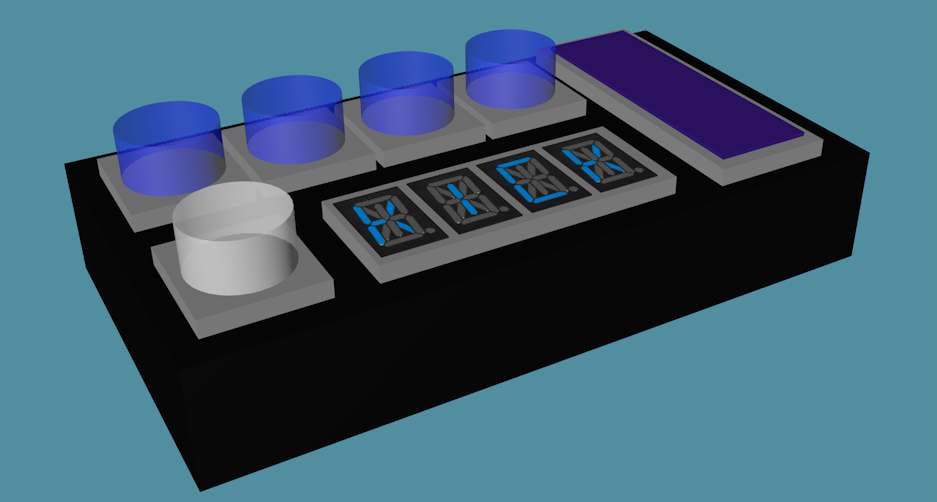
And each beat maps its column to the encoders in the same way. So when you use the knob next to the display to scroll to the next beat, which has a kick, a clap, and an open hat, you see this:
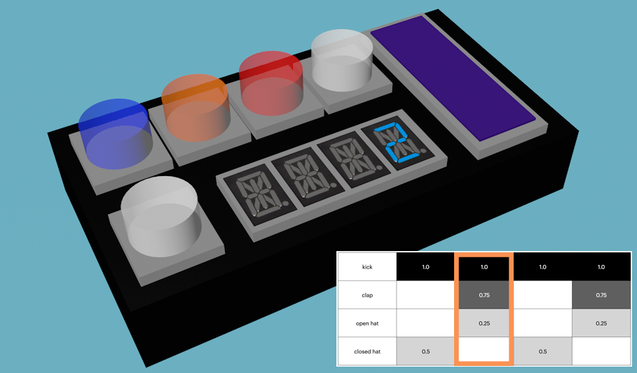
And, as in the previous post, the intensity of the LED would reflect the probability of the drum playing on that beat.
This UI would probably be a little less obvious at first, with a marginally steeper learning curve, but it would look a lot cooler when playing the beat, since it could scroll through the steps as it played. In practice, that would mean a lot of flashing lights. And there’s no reason a drum sequencer built this way couldn’t have 16 steps, or 32, or 64.
Big caveat: since I have no idea how to build a case for this, and this is my first time designing and building my own hardware, it’s probably going to look like a lot more chaotic than these mockups. Still, I think this is a good compromise design.